mseiler
Case Study: Cheap, High Volume Off-the-Shelf Hacker Parts Best Custom Hardware
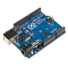
Arduino Uno – Cheap and readily available.
Recently, a client came to me because they were having difficulty getting a $150 interface, associated housing and a further custom PCB. The interface was used between the Ubuntu based controller and the hardware, except for the touch panel display. The hardware consisted of a couple of payment systems, and some dispensing mechanisms, as well as a service switch.
After doing some research, I discovered that I could cover all the required functions using an Arduino Uno and a Grove shield. This combination cost an order of magnitude less than there old design. Along with decreasing the overall cost of the Bill of Materials, the new components could be bought on an as needed basis, greatly reducing stocking expense. Also, because the Arduino Uno is so popular, it it unlikely to go out of production any time soon. Even if it does, the form factor lives on in a variety of more powerful designs.
As I like to point out, we now live in the golden age of prototyping and rapid product ramp up. This is because there is such a wealth of incredibly powerful and cheap components that are available in large quantities, usually from China. This makes it easier than ever before to lash together a prototype, and then turn this into a early production run. The early production run can then be used to validate a market and quickly cycle through user feedback iterations. This all translates in to being able to build product momentum for a market leader. Also, for me personally, it means I get to see my ideas get out into the world at breathtaking speed. For this particular example, the whole redesign, including coding, documentation and acceptance testing, only took about 80 billable hours.

Grove Shield – Makes interfacing a snap.
Kickstarter – Rebooted
It’s taken a couple of years since my last successful Kickstarter to find another Kickstarter worthy idea.
I learned a lot about how the kickstarter marketing funnel works with
https://www.kickstarter.com/projects/1647124460/solar-pi-platter/description
I also put up a “quick and dirty” support site at
http://rocketblueautomation.com/
 Now, 2 years later, we are doing a second production run of the Pi Platter because it continues to sell consistently, and we have a few regular customers.
Mind you, the Pi Platter was never intended to be a “home run,” but rather just a base hit so I could fully appreciate how crowd funding works. Indeed, I learned a lot that will help me on this next “reboot.”
As of this writing, I am still refining the target market. What is clear is that there is a market for a nice case, with a nice user interface and associated code.
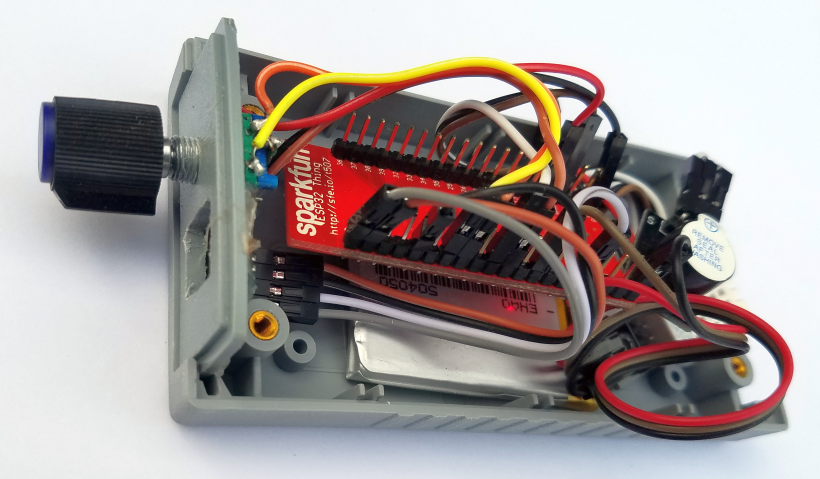
ESP32
One of the things that made the last Kickstarter successful was we had some good examples about how to use our offering – namely the Pi Platter.
For most makers, a polished physical packaging is an afterthought – and often never gets done. This has certainly been the case for me. The user interface consists of a 64×64 oLED display and a rotary encoder with a built in push button switch. So far, I wrote out micropython script to make a temperature/humidity alarm with adjustable set point. The real time interrupts of the rotary encoder where a bit tricky and not surprisingly, micropython was a bit slow on an ESP32. I was curious how well micropython worked, but now that I’ve seen the result, I will redo the code in C. The case is large enough for any number of ESP32, ESP8266 and Arduino boards, including a LiPo battery and charge controller or boost converter. Even a Raspberry Pi Zero will fit.
A couple of candidate niches to sell my new case/UI design to small farm/homestead and the biohackers. I will likely create more than one Kickstarter to cover all the possibilities.
Pi Platter at the Denver Maker Faire
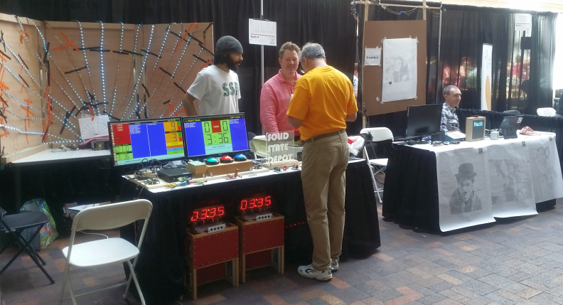
SSD booth at the Denver Maker Faire
On Saturday, June 11, 2016 I had a chance to show off 5 of the Raspberry Pi designs I’ve been working on.
In preparation for a Kickstarter, I’ve been assembling designs that showcase the versatility and usefulness of the “Pi Platter” board I’ve been working on. Dan Julio, the other engineer on the project, and I are both members of the Boulder Hackerspace aka Solid State Depot. The Boulder Hackerspace was invited to the Denver Mini Maker Faire at the Denver Musieum of Denver Museum of Nature and Science.
Introducing the Pi Platter Solar battery charger, USB and RTC board
The Pi Platter board is designed to give the Raspberry Pi Zero, as well at the other models of the Raspberry Pi additional features such as
-
- Additional USB ports
- Solar Li battery charging circuit
- Real Time Clock as well as additional I/O such as PWM outputs and analog inputs
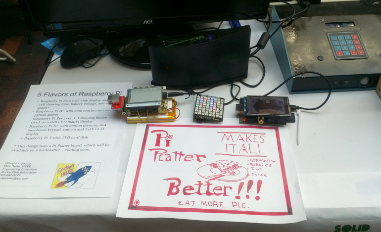
5 Raspberry Pi devices that could use battery backup and RTC
Because the Pi Platter is so versatile, it’s important to showcase some of the ways you can use it. Currently, I have 5 demo designs.
-
-
- Raspberry Pi Zero with eInk display and solar cell showing time, battery voltage, and voltage graph
- Raspberry Pi B+ with mini touchscreen running python games
- Raspberry Pi Zero ver. 1.3 showing binary clock on a 8×8 LED matrix display
- Raspberry Pi B+ Security System with motion detector, 4×4 membrane keypad, camera and 2×16 LCD display
- Raspberry Pi 3 with 1TB hard disk
-
However, because I only have one demo Pi Platter board, I was only able to make one of the designs battery (and solar) powered for the faire. Two key features of all the designs is that they are battery powered and that the GPIO connector is available for HATs – that is daughter boards that fit on top of the Raspberry Pi. The Pi Platter connects through 4 pogo pins to the bottom of the Raspberry Pi Zero and through USB to other Raspberry Pi models.

Close up of 4 of the designs
The Saturday at the faire was a good way to make connections and talk to hob nob with fellow makers.

R2D2 was one of the hits with the kids at the Faire
3 Amazon IoT Button Hacks
The Amazon IoT button is an amazing little device. It can run for about 1000 button presses from the built in lithium AAA battery. It’s easy to connect it to the local WiFi network. But you don’t have to limit yourself to just pressing the button. I present to you 3 additional uses that require only a modest amount of hacking.
Three Amazon IoT Button Uses
I’ve ordered the project from simplest and fastest all the way up to simple and fast. But if you don’t know which end of the soldering iron gets hot, then stick with the first project.
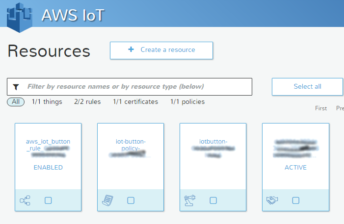
AWS IOT console setup. (The blurred text protects my button)
Door Bell
Stick the Button by your front door (maybe with a label that says “Door Bell”) I have it set up through IFTTT to send me a text, “Somebody is at the front door.” Follow the instructions on the Amazon Button page.
Your Amazon Iot Console should look something like the picture on the right.
Let’s Get Hacking
Prelude – How to safely crack open the “no customer serviceable parts inside” case.
- Remove cover label. You can catch a corner by the tiny microphone hole with the sharp tip of a knife. The label peels off.
- Remove three Torx #5 screws.
- Crack case. Again using a sharp knife tip, carefully wiggle the blade in at the rounded end next to the big button. Don’t do this at the other end because there are electronics close to the edge.
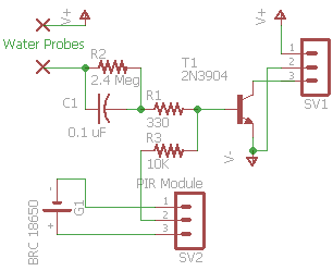
Schematic for both the flood alarm and motion sensor.
The next two hacks bypass the button. A simple additional circuit is added. To prepare solder an access wire to
- the battery plus terminal,
- the battery minus terminal and
- to test point TMF27, which is next to the microswitch that is under the big button. There is a via over part of the ‘7’ which makes it a bit hard to read the number.
Flood Alarm

Flood Alarm using Amazon IoT Button
Here the Button is in my basement, in the utility room. A drop of water simulates a button press, which triggers a rule and texts me, “Flood alarm!” The V+ battery voltage causes a small amount of current to flow into the base of the transistor when water is present at the water probe. R1 is a current limiting resistor which protects the T1 if the probes are shorted together. T1 can be either a 2N2222 or 2N3904 or pretty much any NPN silicon transistor with a gain of around 100. C1 gives a spike or pulse so that the button is only single pressed. SV1 is the connector to the Amazon IoT Button. Pin 1 is the battery +, Pin 2 is the battery -, and Pin 3 goes to test point TMF27, R2 provides a discharge path for C1. (R3, SV2 and G1 are are part of the motion detector and not used for the flood alarm.)
Motion Sensor
A inexpensive HC-SR501 PIR motion sensor is powered by a lithium battery. The PIR motion sensor uses very little current and the 18650 battery should last for years before it needs to be recharged. Again, just about any 3.6 volt lithium battery should work. The 18650 is what I had handly. The PIR motion detectors cost only about a dollar on eBay. R3 provides current limiting to the base of T1, which inverts the signal so that it looks like a button press. The 18650 battery + goes to the pin marked Vcc on the PIR. Likewise, battery – goes to the pin marked GND. Finally the PIR out pin goes to the base of the transistor through R3.
Oh! and I just noticed an error on the schematic. The 18650 battery – goes to pin 2 of SV1. In other words, the ground of the two batteries in the system needs to be connected. The PIR sensor has two setting pots. Set the X1 to minimum (all the way counterclockwise) and the SX pot to the desired sensitivity. The output is sent to the Button. IFTTT texts me, “Movement detected!” The water probe, R2, C1 and R1 are not used for the motion sensor circuit.
Keep in mind that the Amazon IoT button is only good for about 1000 motion detects. This is fine if you are only expecting a few motion triggers a day, but the circuit will only last months or weeks if there are frequent triggers. In case of frequent triggers, you may want to build a power supply. As it says in the text books, “That exercise is left to the reader.”
So, dear reader, does this post give you ideas about what else you can do with an Amazon IoT Button? Let me know!
Update June 20, 2016
Here are two more uses for the IoT button
- A better mouse trap. Modify a regular spring loaded bar mouse trap with a contact closure. The contact closure, of course is picked up by the IoT button by capacitive coupling. This signals that a mouse is ready for “disposal” and that the trap needs to be reset.
- A tapping sensor switch similar to the Knocki. I’m speculating that a piezoelectric energy harvester can trigger the IoT button the knock pattern for a single tap. double tap and maybe even long press. If the piezoelectric sensor does not provide enough energy to trigger the IoT button then we can use a ultra low power op amp to boost the signal.
Raspberry Pi Security Camera

Raspberry Pi Security Camera
I was contacted through the Boulder Hackerspace by someone who wanted help building a Raspberry Pi security camera. We finally settled on the design being a cross between a PiLarm and system that sends pictures to your phone.
The hybrid system has:
- 4×4 membrane keypad for issuing commands
- Magnetic door sensor
- PIR motion detector
- 2×16 backlit LCD status display
- WiFi module
- And of course the the Raspberry Pi and Camera Module
I had a nice aluminum case that fit the display left over from a previous commercial design.
There where some “gotchas” in getting the Python code to work. It was not possible to just mix and match code from the two reference designs.
- Sending the MMS picture does not work with Wheezy, but only with Jessie because Wheezy’s Python 2.7.3 is incompatible with the Twilio import. Jessie provides Python 2.7.9, which works.
- The magnetic door sensor and PIR motion detector code triggered interrupts. This can interfere with the display code if not carefully structured.
- While a code block may work fine by itself, when you combine them you can put quite a demand on the processor. Scanning the matrix keyboard left little time to do anything else.
However, when all was done and said, the final design did a great job of detecting motion or an opening of a door, then taking a picture and texting it to a phone.
A possible next step is to rework this system using a Banana Pi D1, once we can figure out how to reprogram it.
Internet Christmas Tree is a Hit
I’ve modified the fireplace blower controller to control the Christmas tree lights.
At first, I wanted to get the Christmas tree lights to flicker like a candle flame. However, at about the time I programmed in the random function my Particle Photon stopped responding. None of the googled “flashing red light” solutions worked on my Photon. Hmmm, I’ll have to investigate this after Christmas, because trying to get the Photon unbricked was turning into a real time suck.
So, in order to keep moving ahead, I down rev’ed to my Spark Core, which is the previous generation of the Particle Photon. I got it working just in the nick of time. I wanted to show off my IoT Christmas Tree to my nephews and the rest of the family during the Christmas Skype call. Indeed, everyone at the far end of my Skype connection has fun turning the Christmas tree on and off, and changing the flickering characteristics after I gave them my secret web page.
The circuit consists of a Spark Core or Particle Photon, a homebrew optocoupler and a less than $2 AC motor controller from eBay. The optocoupler consists of a green LED which shines on a Light Dependant Resistor (LDR). The LDR is soldered in parallel with the motor speed controller control. The LDR has a lot of capacitance, so it smooth out the pulse width modulation (PWM) output from the Photon. I got the GL5537 Photoresistor from eBay and I had a 10 mA green LED in my junk box. I butted the green LED up against the LDR and held them together with a couple of layers of heat shrink tubing. A resistor of 680 to 1.5K in series with the LED limits current. Comercial versions are made by Vactrol or Silonex. The transfer function is very linear when graphed on a log/log scale.
Hardware costs should be less than $25, most of which is for the Photon.
The software consists of a short program for the Photon that receives commands from the control web page. Follow the links for the code. Make sure to put your own deviceID and accesscode in the beginning of the javascript.
Beyond NEST – Wood Fireplace Insert and Pellet Stove Controller
Previously, I had experimented with an Arudino Uno based fireplace insert blower controller. That experiment evolved in having two displays – one for the time and temperature, another for a graph showing temperature over time.
But, it makes sense to combine the two displays in the previous design into one display. A common, inexpensive display available are 240×320 TFT LCD displays based on the ILI9341 chips. The one I got from Banggood (I couldn’t make up a name like that if I tried!) plugs directly on an Arduino Uno. However, this makes it difficult to find pins for the thermocouple interface. So, I upgraded to an Arudino Mega, which gives me more memory, and oodles of spare I/O ports.
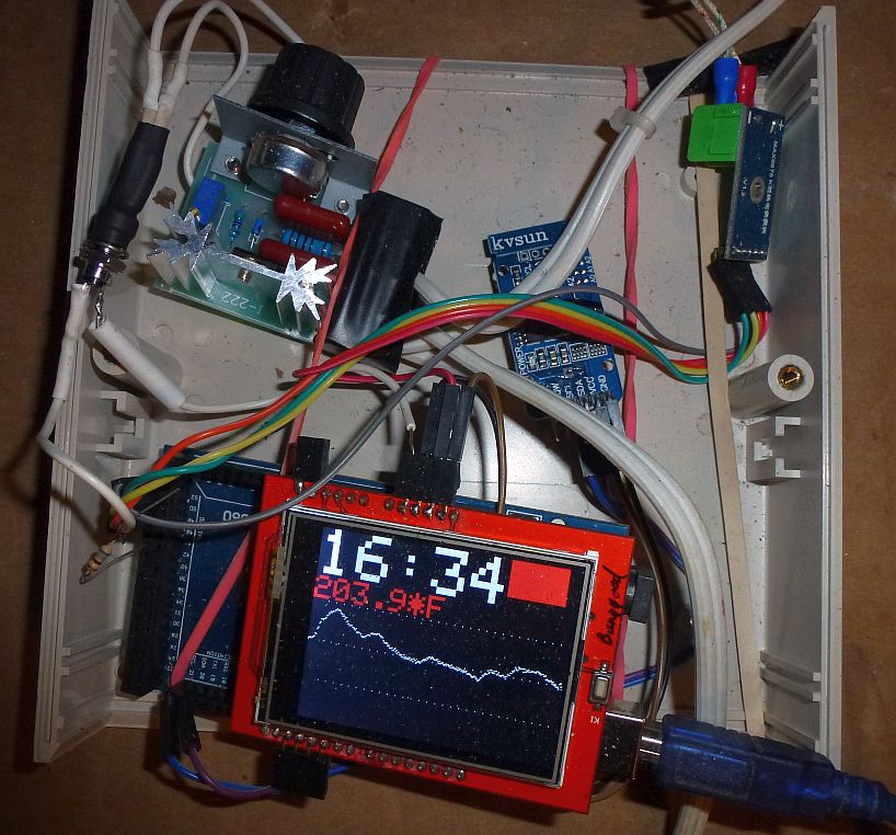
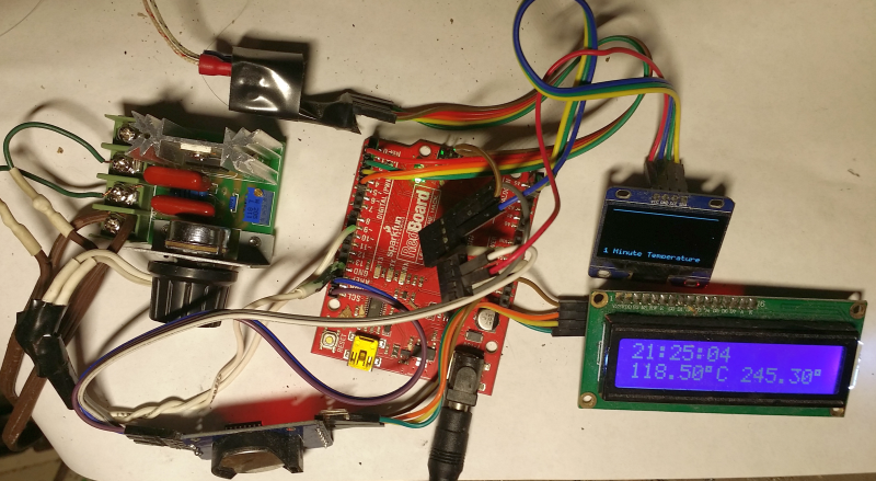
Wood Fireplace Insert Blower controller with graphic display – double click to enlarge.
Note in the picture that the display the time is shown on the first line, temperature on the second line, and then time vs temperature graph below that.
Temperature is graphed once a minute, which makes it easy and entertaining to see the temperature hump created by throwing in a log. A grid with blue dots every 10 minutes and white dots every hour further helps give structure to the graph. Horizontal dots are 50 degrees Fahrenheit intervals. I personally find this graph quite useful for figuring out when, and how big a log to throw on the fire. However, I’m sure I’m going to be dinking with the user interface for quite a while to come.
The DS3231 real time clock (RTC ) from the previous design continues to be on the I2C bus, which is also more accessible with the Mega because the I2C pins are brought out in a second location that is not blocked by the LCD shield.
A few months ago, I did a survey of digitally controlled fan controllers. All the designs seemed more complex and expensive than I though necessary. When I found a AC motor speed controller on eBay for about 2 bucks, I ordered one. In the mean time, I saw a post about using a LDR (Light Dependent Resistor) to complement the variable resistor (Pot) and thought I’d give that a go. By the way, I left the pot in the circuit, so I can bypass the Arduino if I want.
I came up with an Arudino interface consists of a green LED shining onto the LDR , both of which cost about a nickle on eBay. What I don’t understand is why a commercial version (Vactec or Vactrol) of this type of opto-coupler cost $6, when I can build one myself for 2 parts costing a dime, plus a bit of heat shrink tubing. It did not hurt that I already had these parts in my “junk” box. The transfer function my home brew unit is also quite linear if graphed on a log/log scale. The opto-coupler is the nearly vertical black cylinder on the upper left of the picture. However, it’s taking a bit of experimenting to get a good dynamic range and resolution when coupled with the $2 motor speed controller. Selecting the right series resistance for the LED is the key. The LDR has a lot of useful smoothing capacitance and can handle a higher voltage than your typical opto-coupler. The lDR capacitance is useful because the so called Arduino “analog” output is actually pulse width modulation at 750 Hz.
My other reason for creating a second prototype is that I have a pellet stove with a blown controller board in the basement. What it takes to fix it is a blower speed controller – and I now have two working prototypes.
I did a bit of market research and it appears that the market for pellet stoves and fireplace inserts are on the order of hundreds of thousands of units sold in the USA per year. Perhaps there is a path to commercializing my design? I’m going to have to give the design of a demo worthy case some thought.
Wood Stove Fireplace Insert Controller – Beyond NEST
Wood Stove Fireplace Insert Fan Speed Controller with Graphic Display
There are some home temperature control situation that don’t work with a NEST.
In my example, I am controlling the fan speed for the blower of my wood fireplace insert.
I want to be able to control the fan speed depending on stove temperature as well as time of day. In addition, it’s helpful to have a display that graphs the stove temperature for the last couple of hours.
In the prototype, I am showing the time, and blower exhaust temperature in Celsius and Fahrenheit. This forced air is used to heat over 1000 square feet from my fireplace insert.
Modules visible are the arduino UNO, AC fan speed controller, DS3231 real time clock module, 2×16 LCD display, thermocouple interface and 128×64 OLED graphic display. Usually, the graphic display shows a gradual curve as a piece of wood burns.
My next step is to combine the two displays into one 320×240 display (code already written) and put the historical temperature data in the cloud.
Arduino Utility Circuit to Set/Modify DS3231 RTC
I’ve become quite a fan of the DFRobot LCD keypad shield. I’m finding all kinds of little uses for it.
One frequent issue I have is needing to set or modify the DS3231 I2C modules.
So I popped the LCD keypad shield on a Arduino Uno, hooked up the DS3231 module. Then using the simple button interlace to select year, month, day, hour, minute and seconds, I can us the up/down buttons to quickly set or modify the RTC time.
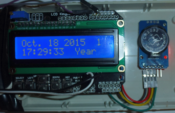
Set the DS3232 RTC clock with a simple Arduino LCD keypad interface.
Here’s the Arduino DS3231 wiring code.
Engineering is Hard, Marketing is Harder
With 20/20 hindsight, I conclude that marketing is harder than engineering.
For example, when I look back at why the success of a product I designed stalled after I sold over 10,000 of them, I can see that this was due to a lack of marketing savvy.
I was fortunate that I was able to ride on the coat tails of an excellent speaker during much of the run up to selling 10,000 units. The speaker would promote my product because he was the inventor of the underlying concept, and he happened to like my implementation. But once my spokesperson retired, I discovered that I did not know beans about marketing.
It took me a few years to realize I need to come up the marketing learning curve. Now, a over a decade later, I find that marketing is still more difficult than engineering. There is no quick and easy formula for fanning the flames of desire.
It comes down to this – It’s easier to design a tangible gadget using engineering design principles than it is to figure out how to elicit enough desire in people to have them part with cold hard cash for said gadget.
I’m not the only one who seems to be having the problem. It is the most common source of startup failure. Specifically, a product is built, and get’s some traction with early adopters. But then, a startup flounders when attempting to broaden it’s market into a larger population of consumers.
A friend of mine did a study of 220 silicon valley startup failures. 87% of the time, the startup money was misspent. Specifically, to much time and money was budgeted for product development, and not enough for marketing.
Ratios vary by industry, but I’ve heard that a successful startup ends up spending twice as much on marketing than on development. If this is true then it points out in dollars and cents terms how difficult marketing is.