Case Study: Off-The-Shelf Parts Make for Rapid Prototyping
Off the shelf components make for a quick prototype
My client wanted to be able to monitor a number of environmental parameters and then respond by turning pumps, fans and heaters on or off. The end result was a optimal plant growth environment in a mini-greenhouse.
I had previously experimented with a odroid Show2. This Arduino Uno type device features a 2.2 inch, 240 x 320 pixel display, 3 switches, 3 LEDs, LiPo battery charging circuit, and a I2C breakout header. There was also a daughter board that turned the Show2 into a weather station.
I realized that this could be the basis for a simplified version of the controller that my client was looking for. By adding additional I2C sensors, and a I2C to 8 bit output, I could take the required readings and turn up to 8 relays on and off.
The client had been working on getting a Beaglebone Black programmed as the brains, but progress was slow. By implementing this “quick and dirty” off-the-shelf prototype, we got a test bed that allowed for faster design considerations. This then gave the project the momentum needed to then make rapid progress.
Arduino IDE and open source rocks!
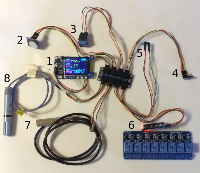
Refer to the above picture for described function:
Not numbered is the “octopus” I2C patch board in the middle. It distributes the I2C bus which is controlled by the display board to the various sensors and outputs.
1. The odroid Display2 is running the (slightly modified) weather program. In this example it is powered by a battery that is glued to the back of the display.
The display is showing the current values from the 3 weather board sensors. Those readings are the “indoor” temperature & humidity, ultraviolet & visible & infrared light levels, temperature (again in both Celsius and Fahrenheit) & pressure & equivalent altitude in feet.
2. Real time clock (RTC) module with button battery. I add this so that the Arduino specs are consistent with Beaglebone specs. Note that the RTC battery typically has a life of 2 to 5 years – at which point it needs to be replaced.
3. The weather board has been relocated from it’s designed position as a daughter board to the display board to a leg of the I2C patch panel. It has the sensors that are currently showing on the display board. The fact that the sensors read correctly indicates that the I2C bus is working properly with the approximately 11 feet of wiring shown in the picture. Although the I2C buss was originally intended for communication between different corners of a PCB, it appears it can be used for longer distances too. At some point I may go back and see how far I2C can practically reach.
4. “Water” temperature sensor. Note that it needs to ruggedized. My intent was to mount it to the outside of the water storage bladder that is in the base of the greenhouse and cover it with a spot of insulation.
5. “External” visible and IR light sensor. As an alternative, this could be the internal sensor because it does not measure UV. The weather board light sensor DOES measure UV. This is significant because the UV will not penetrate through plastic, but it may be helpful to know the UV level “outside.” Personally, I use the UV sensor as guidance for how long to stay out in the mid-day sun.
6. Relay board. The I2C port extender board connects to the relay board with 10 (8 signal + 2 power) wires (not shown.)
7. Ruggedized soil humidity and temperature with 3 foot cable. Adafruit cautions that this $50 sensor should not be immersed in water for more than an hour.
8. Ruggedized “External” air temperature and humidity with 18 inch cable. This is a $30 sensor.
A Quick and Dirty PCB Production Technique
Back in my teens, I experimented with etching my own PCBs. I would draw the circuit with a permanent marker. The thick ink traces acted as a etch resist.
The 21st century upgrade to this technology is the toner transfer method. You print your PCB on a piece of paper. Then you use a clothing iron to transfer the toner from the paper to a copper board. The toner acts as a etch resist and you etch away the rest of the copper using the same chemical process I used decades earlier.
So, how well does this work?
I joined a class given at the Solid State Depot to find out. The instructor was John English and he has the project on github at
https://github.com/johnisenglish/ssd_blinky
We built up the board, but could not get it programmed within the time limits of the class. So, it sat, collecting dust for months until I had the time to have another go at it because I wanted a Christmas mood light project.
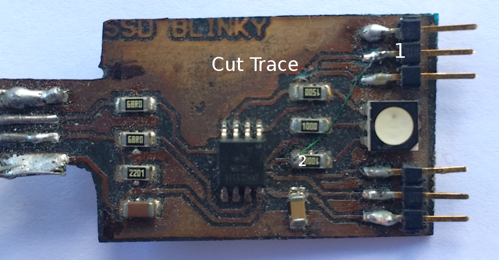
It turned out that in order to get the ISP (In System Programmer) to work, I need to fix a trace routing mistake. Specifically, I cut the trace show below the “e” of “Cut Trace” in the picture. In place of the cut trace, I ran a fine green wire from point 1 to point 2. By the way, the wire is made with special insulation that melts cleanly when heated with solder. I’ve not been able to locate more of this handy wire in over a decade.
Once I got board debugged, I decided that the RGB light would make a great mood light. Sure, you can get mood lights cheaply from eBay, but I wanted to program a mood light with my own artistic flair. Specifically, I wanted to explore the balance between randomness and predictability for the perfect hypnotic effect.
Fortunately, the Arduino IDE has been extended to work with the blank chip used in this project. Programming was done over the ISP interface once the board was debugged
Because the Atmel 2586 AVR chip only had two timers and a RGB LED suggests the need three timers, I decided to do the pulse width modulation entirely in software.
I wish that I could show the arduino wiring code with all the pretty color enhanced highlights from the arduino IDE. I was aiming to create a hypnotic, flickering mood light.
/*
RGB Mood light using SSD Blinky board – Mike Seiler
*/
#define GREEN_LED PB0 // Green LED
#define BLUE_LED PB1 // Blue LED
#define RED_LED PB4 // Red LED
#define UP 1 // Increase pulse width
#define HOLD 0 // keep pulse width the same
#define DOWN -1 // decrease pulse width
// randomly choose to increase, hold or decrease pulse width.
// this creates flickering fades of one color into another.
unsigned short color_direction( unsigned short direction){
long val;
val = random()%8;
if (val==0) direction = UP;
if (val==1) direction = HOLD;
if (val==2) direction = DOWN;
// Serial.println(direction);
return (direction);
}
// standard arduino function
void setup() {
// initialize serial and wait for port to open:
Serial.begin(9600); // for testing code
DDRB |= (1 << GREEN_LED); // LED green Pin set to output
DDRB |= (1 << RED_LED); // LED red Pin set to output
DDRB |= (1 << BLUE_LED); // LED blue Pin set to output
// send an intro:
Serial.println(“\n\nMood light test:”);
Serial.println();
}
void loop() {
unsigned short red_direction=1, green_direction=1, blue_direction=1;
unsigned short red_level=40, green_level=1, blue_level=20; // initial values
char teststring[20];
while(1) // do forever
{
red_direction = color_direction(red_direction); // randomly change red pulse width
red_level += red_direction;
if (red_level > 252 ) red_direction = DOWN; // “bounce” off limits
if (red_level < 3) red_direction = UP;
green_direction = color_direction(green_direction); // randomly change green pulse width
green_level += green_direction;
if (green_level > 252 ) green_direction = DOWN; // “bounce” off limits
if (green_level < 3) green_direction = UP;
blue_direction = color_direction(blue_direction);// randomly change blue pulse width
blue_level += blue_direction;
if (blue_level > 252 ) blue_direction = DOWN; // “bounce” off limits
if (blue_level < 3) blue_direction = UP;
sprintf(teststring, “%d %d %d”,red_level,green_level,blue_level); // for testing
Serial.println(teststring);
delay(100);
}
}
The Profound Implication of Moore’s Law
To be sure, Ray Kurzweil has built an entire career riding the leading edge of Moore’s Law. He does a better job than I ever could of expounding on it’s significance.
However, let me add my two cent’s worth.
It has been hypothesized that there is a direct relationship between our civilization energy consumption, and continued population growth. In short, energy, not food, fuels our population growth. (Aside: low cost energy makes it easier to produce food cheaply.) http://www.resilience.org/stories/2009-04-20/peak-people-interrelationship-between-population-growth-and-energy-resources
There is concern that once we pass “peak energy” that we will see massive depopulation as our energy supply dwindles. (Now that can’t be good.)
I’d like to propose that Moore’s law may come to our rescue… at least for a while. You see, not only do computers become more efficient as a byproduct of their increasing capacity – but this increased efficiency spreads into the rest of our environment. As a minor example, cars are more efficient in part because of the computers they now contain. However the current best example is how smart phones make all of us more efficient in countless ways.
However, the tend of every faster, smaller, cheaper computers making us more efficient is just getting started. The next few years will see an explosion of the “Internet of things.” (IoT) The IoT means that or things will gradually become more and more interconneted and intelligent.
What’s the driving force for this trend? Efficiency and/or convenience – of course! As our environment becomes more responsive to us (because it is intelligent) it will further make us efficient, which will save time, money, and most importantly, energy.
This increased energy efficiency will delay the day that “peak energy” exerts a downward pressure on economies and population. Thus, Moore’s Law may delay the day this civilization runs out of energy and with that, the ability to feed ourselves.
P.S. Yes, I can hear the naysayers asking, “What about super intelligent machines taking over everything?” Let me just add that to my list of subjects for a further blog post.
This is the Golden Age of Electronic Tinkering
Moore’s Law is an observation that the number of transistors on a chip will double every two years. Or put another way, it will cost half as much for a given number of transistors every two years.
In the 3+ decades that I’ve observed the electronics industry in, I continue to be amazed at how Moore’s Law has profound implications for… just about everything. Now, this statement deserves it’s own blog post, but let me stay on point and give an example of how it has made electronic tinkering so much fun.
Case in point
Ordered upconverter from ebay last April because it was so cheap, I wanted to have one handy because I might need one some day.
Also, got LiPo battery, holder and charger from Sparkfun because it might be useful some day.
At the Solid State Depot, I saw Santa hat with RGB LED lights.
I had just happened to have just programmed a hypnotic RGB mood light on a PCB. Now could I make this all portable?
Bada bing, bada boom – I hooked up the charger and upconverter to the LiPo battery so I could power the RGB LED mood light PCB. Almost instantly, I had a very useful rechargeable project I could slide into the brim of a Santa hat.
As a final thought, I should mention that Moore’s law is gradually taking over areas beyond computers. Audio, photography and telephony have already succumbed. Transportation, and various areas of expertise appear to be next.