A Quick and Dirty PCB Production Technique
Back in my teens, I experimented with etching my own PCBs. I would draw the circuit with a permanent marker. The thick ink traces acted as a etch resist.
The 21st century upgrade to this technology is the toner transfer method. You print your PCB on a piece of paper. Then you use a clothing iron to transfer the toner from the paper to a copper board. The toner acts as a etch resist and you etch away the rest of the copper using the same chemical process I used decades earlier.
So, how well does this work?
I joined a class given at the Solid State Depot to find out. The instructor was John English and he has the project on github at
https://github.com/johnisenglish/ssd_blinky
We built up the board, but could not get it programmed within the time limits of the class. So, it sat, collecting dust for months until I had the time to have another go at it because I wanted a Christmas mood light project.
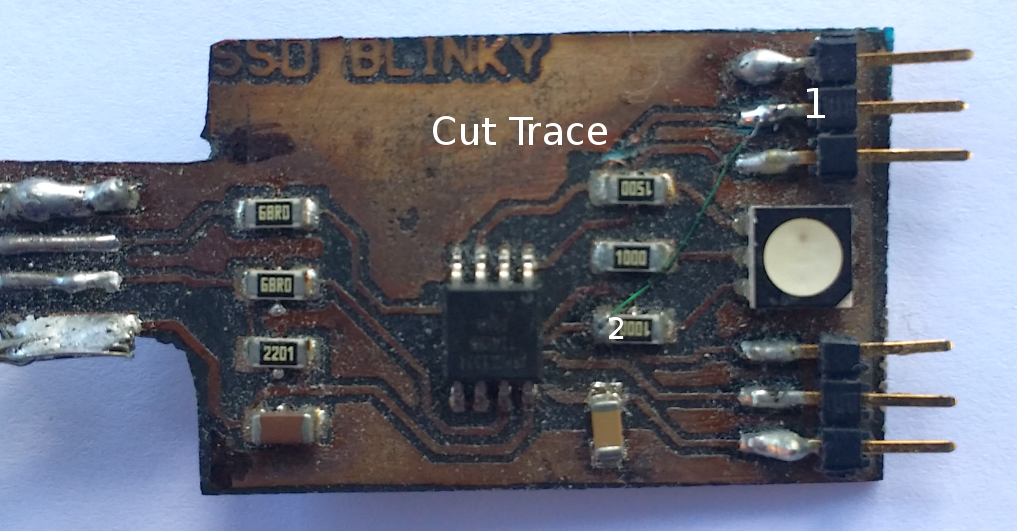
It turned out that in order to get the ISP (In System Programmer) to work, I need to fix a trace routing mistake. Specifically, I cut the trace show below the “e” of “Cut Trace” in the picture. In place of the cut trace, I ran a fine green wire from point 1 to point 2. By the way, the wire is made with special insulation that melts cleanly when heated with solder. I’ve not been able to locate more of this handy wire in over a decade.
Once I got board debugged, I decided that the RGB light would make a great mood light. Sure, you can get mood lights cheaply from eBay, but I wanted to program a mood light with my own artistic flair. Specifically, I wanted to explore the balance between randomness and predictability for the perfect hypnotic effect.
Fortunately, the Arduino IDE has been extended to work with the blank chip used in this project. Programming was done over the ISP interface once the board was debugged
Because the Atmel 2586 AVR chip only had two timers and a RGB LED suggests the need three timers, I decided to do the pulse width modulation entirely in software.
I wish that I could show the arduino wiring code with all the pretty color enhanced highlights from the arduino IDE. I was aiming to create a hypnotic, flickering mood light.
/*
RGB Mood light using SSD Blinky board – Mike Seiler
*/
#define GREEN_LED PB0 // Green LED
#define BLUE_LED PB1 // Blue LED
#define RED_LED PB4 // Red LED
#define UP 1 // Increase pulse width
#define HOLD 0 // keep pulse width the same
#define DOWN -1 // decrease pulse width
// randomly choose to increase, hold or decrease pulse width.
// this creates flickering fades of one color into another.
unsigned short color_direction( unsigned short direction){
long val;
val = random()%8;
if (val==0) direction = UP;
if (val==1) direction = HOLD;
if (val==2) direction = DOWN;
// Serial.println(direction);
return (direction);
}
// standard arduino function
void setup() {
// initialize serial and wait for port to open:
Serial.begin(9600); // for testing code
DDRB |= (1 << GREEN_LED); // LED green Pin set to output
DDRB |= (1 << RED_LED); // LED red Pin set to output
DDRB |= (1 << BLUE_LED); // LED blue Pin set to output
// send an intro:
Serial.println(“\n\nMood light test:”);
Serial.println();
}
void loop() {
unsigned short red_direction=1, green_direction=1, blue_direction=1;
unsigned short red_level=40, green_level=1, blue_level=20; // initial values
char teststring[20];
while(1) // do forever
{
red_direction = color_direction(red_direction); // randomly change red pulse width
red_level += red_direction;
if (red_level > 252 ) red_direction = DOWN; // “bounce” off limits
if (red_level < 3) red_direction = UP;
green_direction = color_direction(green_direction); // randomly change green pulse width
green_level += green_direction;
if (green_level > 252 ) green_direction = DOWN; // “bounce” off limits
if (green_level < 3) green_direction = UP;
blue_direction = color_direction(blue_direction);// randomly change blue pulse width
blue_level += blue_direction;
if (blue_level > 252 ) blue_direction = DOWN; // “bounce” off limits
if (blue_level < 3) blue_direction = UP;
sprintf(teststring, “%d %d %d”,red_level,green_level,blue_level); // for testing
Serial.println(teststring);
delay(100);
}
}